A1000 Variable Speed Drive Model Ratings and Dimensions
March 17, 2011Frequency To Voltage Module General Description
May 10, 2011Electronic MOP Module MOP250-000

General Description • Standard Features • Specifications • Dimensions • Connections

General Description
Historically, this feature was implemented by connecting a motor shaft to a potentiometer. INCREASE and DECREASE buttons could then be used to slowly rotate the motor one direction or the other, thus changing the output signal from the potentiometer. Multiple buttons could be wired in parallel, allowing INCREASE and DECREASE adjustment in multiple locations. This setup was called a Motor Operated Potentiometer (MOP), or motorized potentiometer.
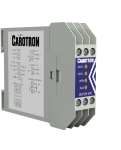
Model MOP250-000 (Electronic Motor Operated Potentiometer Module) is a motorized potentiometer that provides the MOP function in an small DIN rail mountable electronic package. The module has dedicated inputs for INCREASE and DECREASE pushbuttons. Pressing both inputs simultaneously, serves as the RESET function, causing the output to instantly drop to minimum. Opening the ENABLE input forces the output to ramp down to minimum output. Closing the ENABLE input forces the unit to ramp back up to the previous level.
Additionally, an EXTERNAL REF input allows the MOP to ratio (scale) an external signal if desired. Multiturn potentiometers are provided for adjusting the ACCEL, DECEL, BIAS, and GAIN settings. An internal jumper allows selection of a voltage or current output. Internal EEPROM is used to backup and retain the current MOP output during a power loss.
Literature
Drawings
For more information about this product,
call 1-888-286-8614 or e-mail us today!
General Description • Standard Features • Specifications • Dimensions • Connections
Back to System Interface Components • Back to Product Line
