CSAG Multiple Drives – Coordinated Control
March 26, 2010CSAG Surface Driving Rolls and Take-ups
March 26, 2010Dancer Control Systems: A Look at Dancer Positioning and Compensation
In general, dancer control or compensator mechanisms and their position sensors are incorporated into velocity mode drive applications for several reasons.
They can provide accumulation or storage of material. When located between two driven sections of a process that may accelerate or decelerate at different rates, the dancer can absorb or store excess material or give up stored material to provide a more stable operating tension level.
How much material a dancer can store in its acceptable range of movement is “running time storage.” More running time storage allows longer response times in the controlled drives and motors and usually results in more stable operation.
With a conventional gravity-operated “swing arm” type dancer, maximum storage equals the length of web material required to drop the dancer from its highest possible position to its lowest possible position. This range of movement is rarely acceptable in real life and would usually cause a dancer “travel limit” fault to occur. True “running time storage” is the length stored in the range of movement that is acceptable by the person(s) qualifying successful operation. Systems supplying 0.5 to 1.0 second or greater running time storage seldom encounter set-up difficulties, though less storage can still be successful with careful adjustment and by minimizing the range of the dancer control circuit.
Since the force exerted by a dancer sets the Tension in the zone where it’s located, the dancer can be used as a direct Tension controlling device when used with adjustable weights, counterweights or pneumatically controlled actuators. Electrically controlled pneumatics can be used to provide Taper Tension control.
A dancer roll tension control system can use the principle of inertia compensation to absorb upsets in tension while keeping web tension consistent throughout the process. Engineers can create inertia compensation by balancing the inertias of the up-and-down motions of the dancer with the rotating inertias.
1. Dancer Utilization
How dancer control can best be utilized depends on the answers to several questions:
- What is used as the dancer position sensor, and what kind of signal does it provide?
- Will the dancer provide 100% of the reference signal to the drive being controlled, or will it be used to provide a lower percentage correction or trim?
- What is the material maximum “line” speed, and how much running time storage is provided by the dancer mechanism?
- Will the dancer provide a fixed or variable operating tension level, and is Taper tension control required?
2. Dancer Sensors
The most common sensor used to signal the dancer position is a potentiometer. There are many “pot” types with different materials and construction features used in their manufacture. Unfortunately, standard pots meant for manual operation are often used in these applications with several negative results:
- Limited life expectancy due to excess wear of the resistance element: Dancer pots, unlike manual pots, are rotated very frequently if not continuously during their operating life. When used successfully with dancer position or PID circuits, their wear is actually concentrated around a single spot in their rotation range which greatly increases the equivalent number of rotations.
- Limited life expectancy due to excess wear of the shaft bushing: Dancer pots are usually coupled to the pivot point shaft of the dancer mechanism by a sprocket and chain or gear and timing belt arrangement. Tightening the belt or chain to prevent “lost motion” causes lateral wearing forces on the bushing not usually seen with a manually operated knob.
- Limited life expectancy due to rotation beyond physical limits: Most conventional pots have a 270 degree electrical and mechanical rotation. The pots have physical rotation “stops” integrated into their construction – a good thing with a manual adjustment but very bad when the pot becomes the travel limiter for a dancer mechanism.
Carotron addresses and solves each of these problems in our Dancer Duty Potentiometer series of products and with our Non-Contact Sensor products.
Applicable Products
- WDDC1 & WDDC2 Washdown Duty Dancer, Process Current Sensor Series
- WDDV1 & WDDV2 Washdown Duty Dancer, Voltage Output Sensor Series
- NCD01 & NCD02 Non-Contact Dancer Sensor Series
- DDP01 & DDP02 Dancer Duty Pot Series
- MTPS-16-010 Teachable Multi Turn Position Sensor
3. Dancer Mechanical Performance
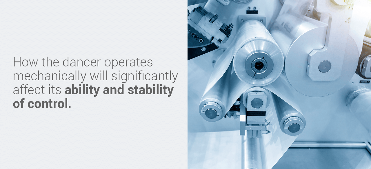
How the dancer operates mechanically will significantly affect its ability and stability of control. The dancer control mechanism must move freely and track robustly with the material. Pneumatics used to control dancer operating force must not restrict or dampen movement with a “shock absorber” effect.

There must be no movement of the dancer that is not reflected or indicated by signal change from the sensor. Loose couplings, chains, timing belts, sprockets, gears, etc. used to translate dancer movement to sensor output can result in poor dancer system performance if not outright instability.
4. Dancer Control Techniques
The following lists several dancer control systems to keep tension at an appropriate level.
- Dancer trim
- Shunt field trim by dancer
- PID trim control
- PID 100% control
Dancer Trim
The purpose of Dancer Trim web tension controllers is to provide a small speed correction between two driven points on a web. An “actual speed” signal, taken from the leader drive, will be trimmed by the dancer control mechanism with its associated position sensor. Operation is much like a Basic Follower scheme except that the Trim function is implemented by a mechanical dancer mechanism instead of manually.
Without dancer control, a speed mismatch may result from differences in loading and in acceleration and deceleration times or may come from individual drive speed regulation errors. In a dancer compensated system, when follower speed errors occur, the dancer is pulled out of position until it produces a countering and balancing speed trimming signal. The exact position of the dancer may change at different set speeds but is usually consistent at a given speed.
Shunt Field Trim by Dancer
With a single DC drive controlling more than one “shunt field” motor, a traditional method for dancer trim used a dancer driven wire wound field trim rheostat (variable resistor) placed in series with one motor’s field circuit. In these systems, the two motor armatures were connected to a single drive’s armature output. This would make the motors run together except for those errors mentioned previously.
This high wattage rheostat was sized to add to the motor’s field resistance, thereby decreasing the field current and increasing motor speed. This type of compensation, still used today in some limited speed range applications, is very simple, but it has the drawbacks of high rheostat operating power and temperature, non-linear correction, decreased motor torque. It was also effective only over a total approximate speed range of 4:1. A more modern variation of DC field control replaces the rheostat with an electronic Field Current Regulator.
Applicable Products
With dancer trim of a drive’s speed reference, the simplicity of field trim web tension control systems is duplicated, but a wider speed control range is possible with better control linearity. It can also be used with permanent magnet DC motors and AC Inverter systems.
PID Trimming
Implementation of PID control as a speed trimming function for dancer positioning is similar to the dancer trim application except the control circuit must provide the required speed trimming signal while keeping the dancer in the same physical position. Refer to Section E.5, PID Control, for discussion on PID loop operation.
The keyword for this section of discussion is Trim. Due to restrictions and/or limitations imposed by the use of dancers, i.e. mechanical response, storage time, etc., it is usually better to utilize a dancer and associated circuitry with a limited control or trim range. This fact is even truer when Load Cells or tension transducers are used for feedback. This requires that the primary reference for the dancer trimmed drive comes from a different source such as a Master Reference, Follower or a Multiplier/Divider function control circuit. Limiting the dancer control system range also permits optimization of the “dancer loop” circuitry for faster response and greater accuracy without sacrificing stability.
Applicable Products
- CLT2000-000 Cortex LT Controller
- D10541-000 Dancer Position/PID Card
- MM3000-PID Micromanager PID Control
Full PID Control
PID control is often thought of as an unclear method. The challenge lies in adjusting controllers for correct operation, which can be difficult for those less familiar with PID control methods. Some of the variables to consider include:
- Speed of the controlled material.
- The amount of pressure or tension required.
- Elasticity of material.
- Proportional (P gain ), which provides a medium time response.
- Differential (D gain ), which provides a fast time response.
- Integral (I gain), which provides a slow time response. A simple dancer position control circuit is shown in figure F.2. Examples of PID control providing a speed “trimming” function are shown in Section H: Center Driven Winders and Unwinders.
Applicable Products
- CLT2000-000 Cortex LT Controller
- D10541-000 Dancer Position/PID Card
- MM3000-PID Micromanager PID Control
Optimize Tension Control With Carotron
Carotron understands the importance of maintaining optimal dancer roll tension control in any application. If you are interested in meeting the challenges of optimizing tension control, Carotron is here to help. Contact us with the requirements of your application. Our experienced engineers can assist you with recommendations or provide you with more information on Carotron products and services.


